Что это?
При необходимости получить трехмерную модель объекта методом 3d-фотосъемки для повышения качества результата и упрощения процесса используют поворотный стол – автоматически вращающуюся на 360 градусов платформу. На рынке представлено большое разнообразие моделей разного размера и сложности реализации, но в целом устройство представляет собой сочетание простейших компонентов, повторить и собрать свой вариант которого сможет каждый заинтересовавшийся любитель!
What is it?
When it is necessary to get a three-dimensional model of the object by the method of 3d-photography, quality of the result can be improved and process can be somplified with usage of turntable - automatically rotating on 360 degree platform. Wide variety of different size and complexity models are already represented in the market, but in general the device is a combination of the simpliest components and can be rebuild by every inspired amateur!
Что нам понадобится?
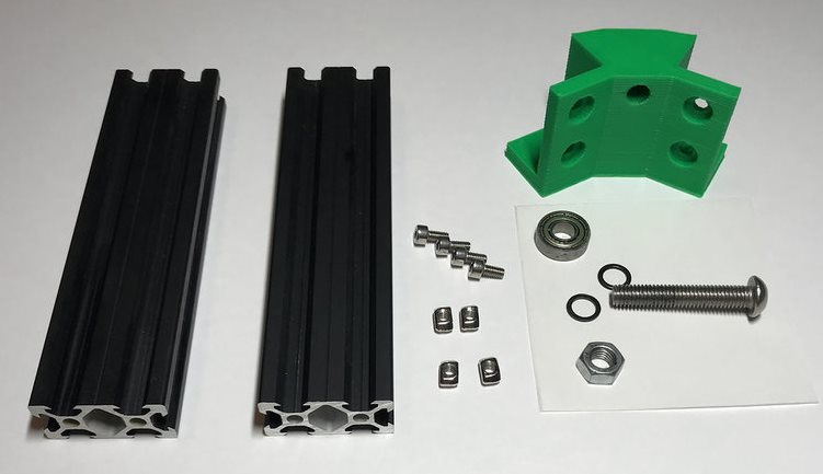
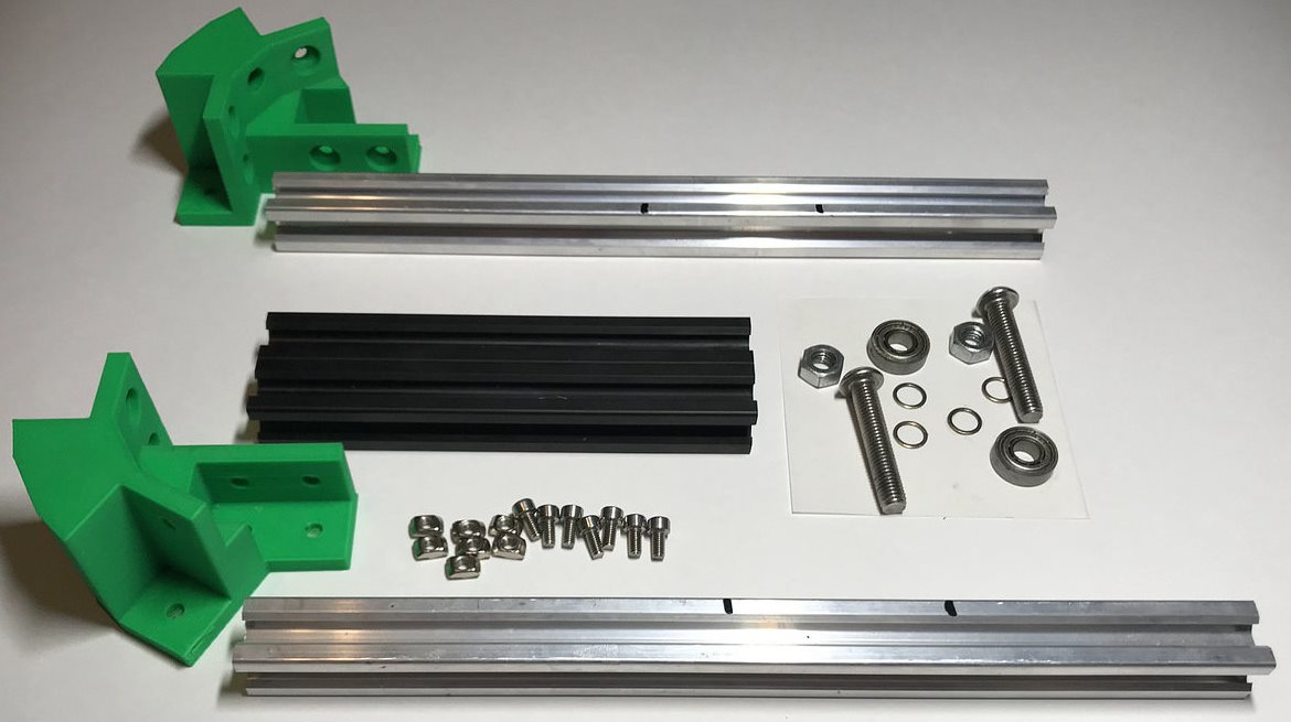
Основные детали:
Алюминевый профиль:
-
20x20x150 I-Typ Nut 5
- x1
-
20x20x260 I-Typ Nut 5
- x2
-
20x40x150 I-Typ Nut 5
- x6
Детали, распечатанные на 3d-принтере:
-
Угловое крепление цельное
-
Угловое крепление с отверстием
-
Соединитель центральный правый
-x2
-
Соединитель центральный левый
- x2
-
Крепление центральной планки
- x2
-
Крепление для управляющей платы (Iskra Neo)
-
Крепление двигателя
-
Крепление для блока питания
-
Крепление драйвера двигателя
-
Стяжка проводов
- x3
-
Шестеренка с креплением к столешнице
-
Шестеренка на вал двигателя
Фурнитура:
-
Винт M4X8 DIN912
- x52
-
Т-гайка М4, паз 6, H29
-
Ходовой вал d=8mm L=52mm
-
Подшипники D16 d8 h5
- x2
-
Подшипники D19 d8 h6
- x6
-
Шайбы
-
Винт M8x45
- x6
-
Гайка M8 - x6
-
Винт M3X8
- x4
-
Кнопка-выключатель
-
Провода
What do we need?
Main parts:
Aluminum profile:
-
20x20x150 I-Typ Nut 5
- x1
-
20x20x260 I-Typ Nut 5
- x2
-
20x40x150 I-Typ Nut 5
- x6
3d-printed parts:
Hardware:
-
Screw M4X8 DIN912
- x52
-
Т-nut М4, паз 6, H29
-
Running shaft d=8mm L=52mm
-
Bearings D16 d8 h5
- x2
-
Bearings D19 d8 h6
- x6
-
Spacers
-
Screw M8x45
- x6
-
Nut M8 - x6
-
Screw M3X8
- x4
-
Switch button
-
Wires
Как это собрать?
-
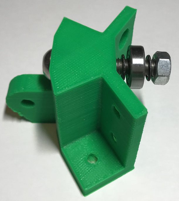
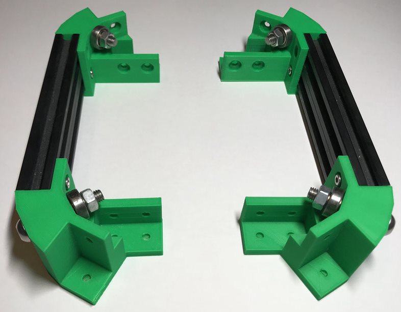
Боковые детали:
 ×
×-
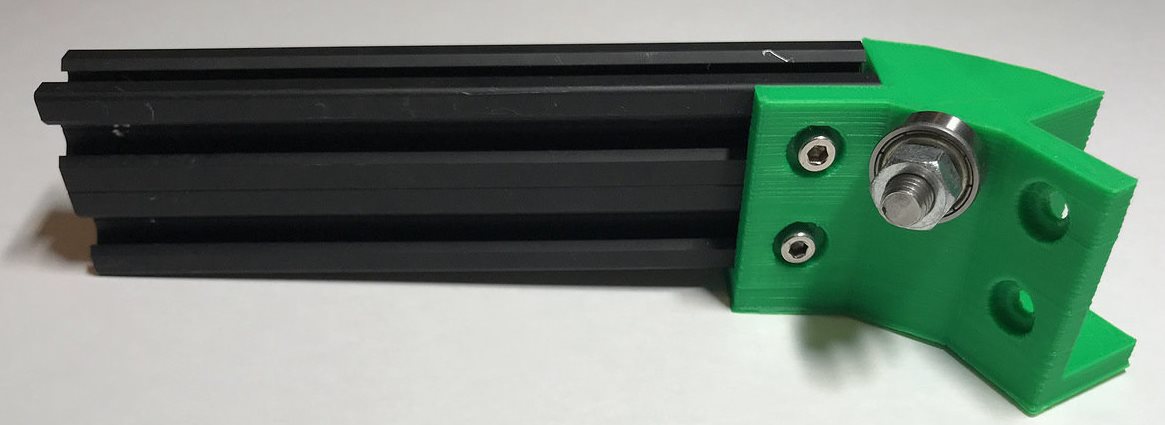
Вкрутите в центральное отверстие углового крепления винт М8Х35 и наденьте на него шайбу-подшипник D19-шайбу-гайку M8 и закрутите гайку до упора:
 ×
× ×
× -
Прикрутите детали профиля 20Х40 к угловым креплениям с помощью винтов M4X8 и Т-гаек M4:
 ×
× ×
× -
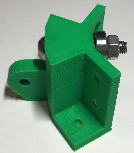
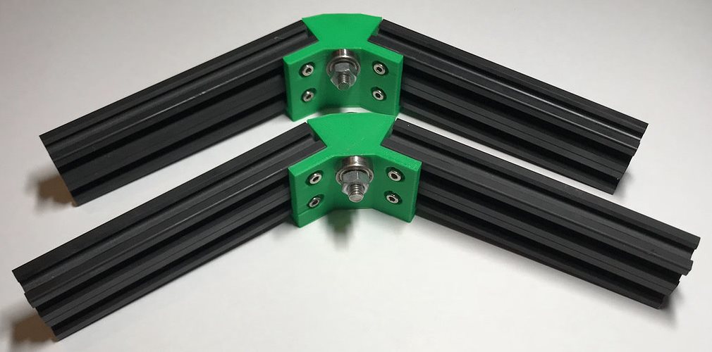
Повторите процесс сборки для получения второй боковой детали:
 ×
×
-
Вкрутите в центральное отверстие углового крепления винт М8Х35 и наденьте на него шайбу-подшипник D19-шайбу-гайку M8 и закрутите гайку до упора:
-
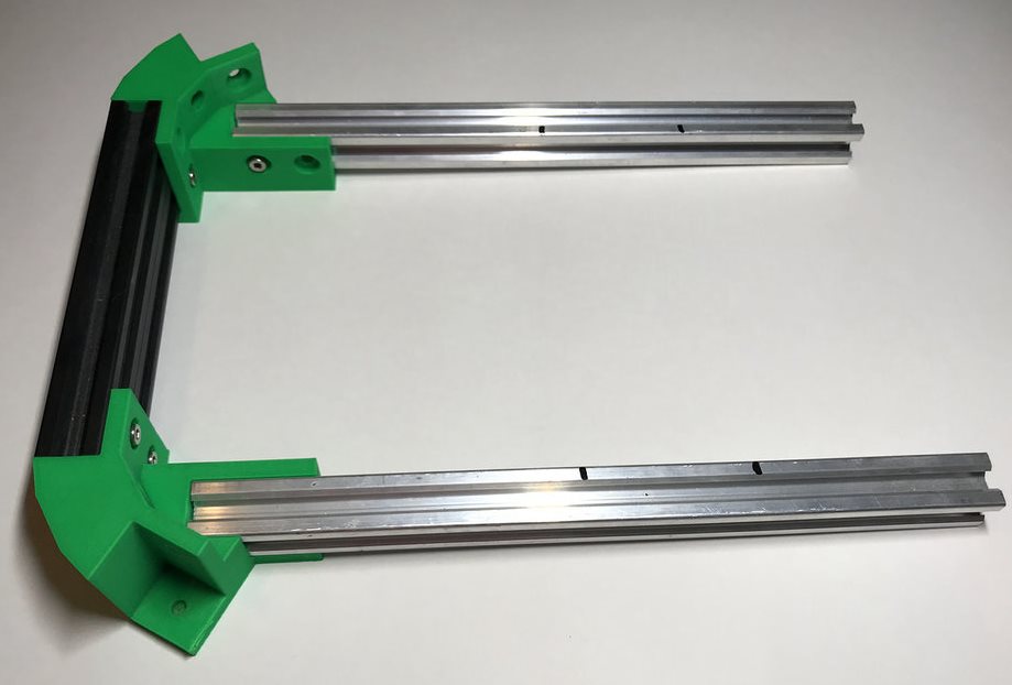
Центральная деталь:
 ×
×-
Соедините центральное левое и центральное правое крепление профилем 20Х40:
 ×
× -
Повторите процесс сборки для получения аналогичной детали:
 ×
× -
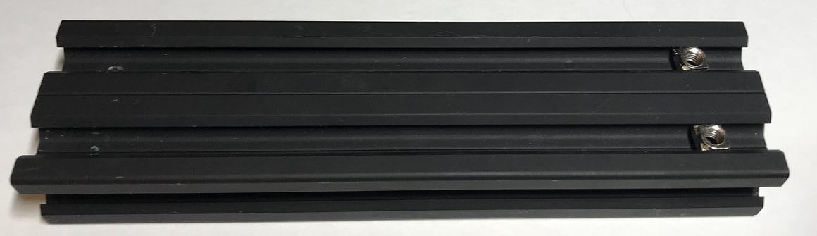
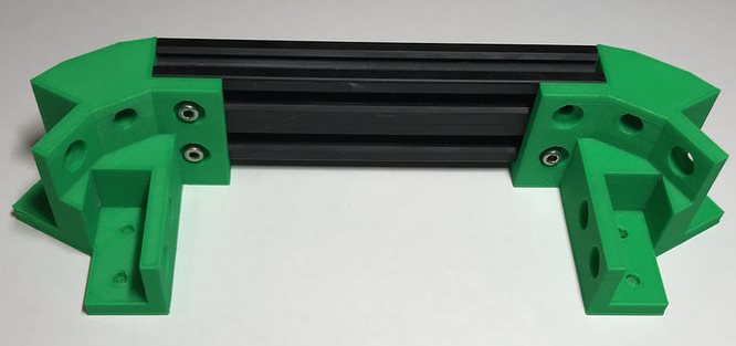
Вложите детали профиля 20Х20Х260 в пазы и закрепите винтами M4X8 и Т-гайками:
 ×
× -
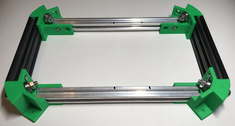
Закрепите вторую деталь на противоположных концах деталей профиля 20Х20Х260:
 ×
× -
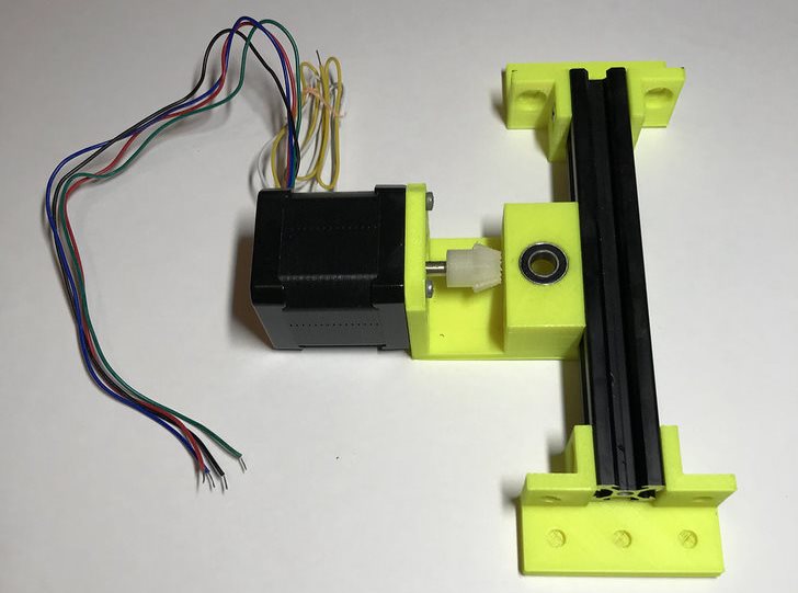
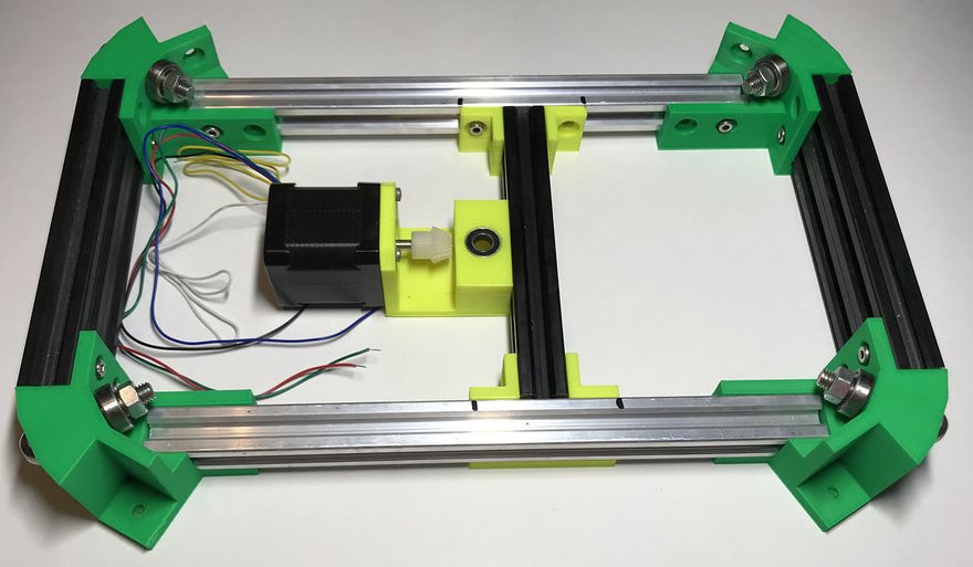
Закрепите на детали профиля 20Х20Х150 крепление двигателя и
два крепления центральной планки с помощью винтов M4X8 и
Т-гаек, закрепите шестерёнку
на вале двигателя и прикрутите его к креплению:
 ×
× -
С помощью винтов M4X8 и Т-гаек прикрутите крепления центральной
планки к деталям профиля 20X20X260 (!соблюдая разметку!):
 ×
×
-
Соедините центральное левое и центральное правое крепление профилем 20Х40:
-
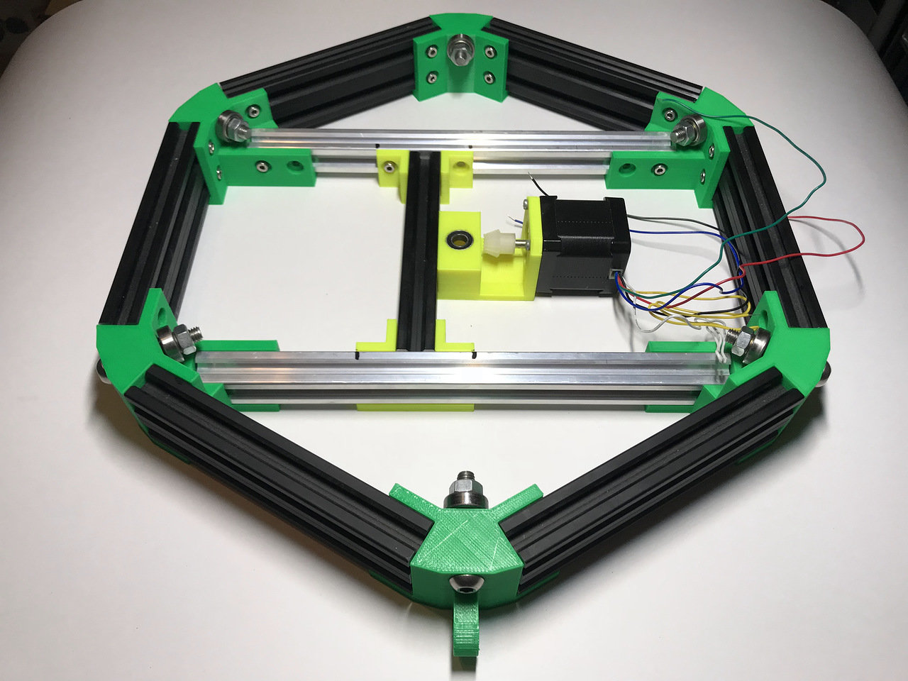
Прикрутите боковые детали, собранные на шаге 1, к центральным соединителям:
 ×
× -
Hardware:
-
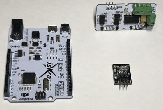
Подготовьте плату IskraNeo, драйвер шагового двигателя и ИК-приёмник:
 ×
× -
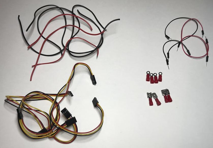
Подготовьте провода и клеммы для соединения устройств и подключения питания:
 ×
× -
С помощью обжимных клещей и паяльника подготовьте следующие провода:
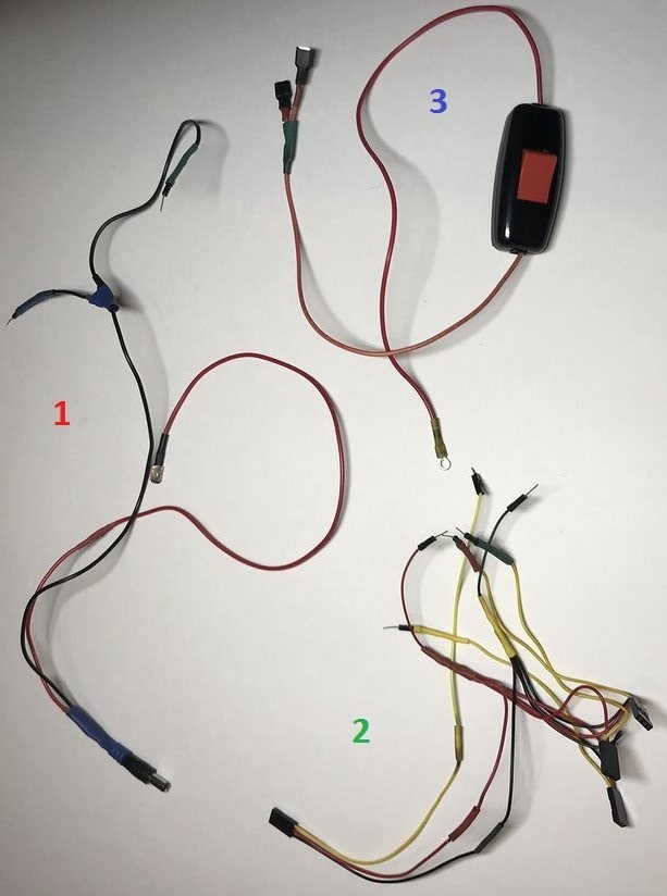 ×
×1 Питание IskraNeo и N драйвера двигателя 2 Подключение драйвера двигателя и ИК-приемника к IskraNeo ( +/- x4 и 4 провода, передающие сигнал) 3 Кнопка включения платы и драйвера двигателя
-
Подготовьте плату IskraNeo, драйвер шагового двигателя и ИК-приёмник:
-
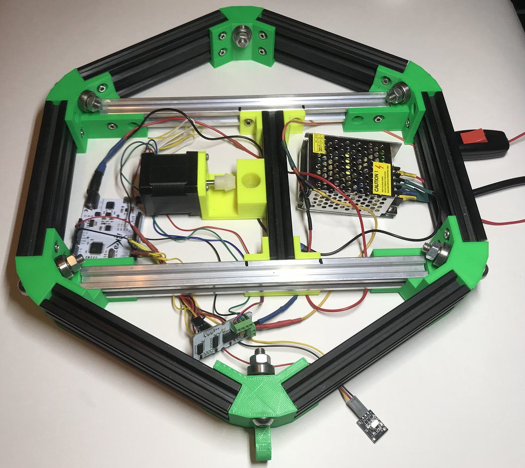
Подключите IskraNeo и драйвер двигателя к блоку питания согласно схеме:
 ×
× -
Вставьте в крепление двигателя подшипники D16.
-
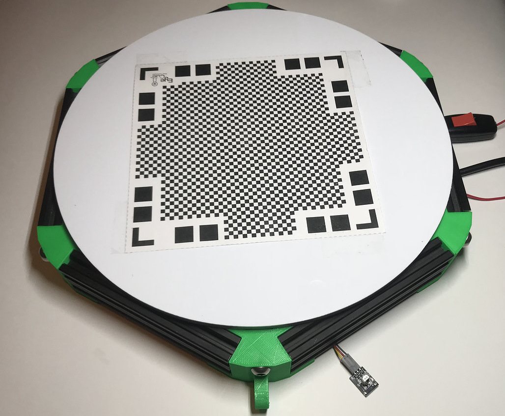
Закрутите вал в крепление с шестеренкой и закрепите его на столешнице.
-
Вставьте столешницу с валом в подшипники:
How to assemble it?
-
Side parts:
×-
Screw M8X35 into the central hole of the corner mount and put on - spacer-bearing D19-spacer-nut M8 - and tighten the nut until it stops:
×
× -
Screw the 20X40 profile parts to the corner mounts using the M4X8 screws and M4 T-nuts:
×
× -
Repeat the assembly process to get a second side part:
×
-
Screw M8X35 into the central hole of the corner mount and put on - spacer-bearing D19-spacer-nut M8 - and tighten the nut until it stops:
-
Central part:
×-
Connect the center left and center right mount with 20X40 profile:
× -
Repeat the assembly process to obtain a similar part:
× -
Insert the 20X20X260 profile details into the grooves and secure them with the M4X8 screws and T-nuts:
× -
Fasten the second part to the opposite ends of the 20X20X260 profile parts:
× -
Fasten the engine mount to the 20X20X150 profile parts and
two central brackets with M4X8 screws and T-nuts, fix the
gear on the engine shaft and screw it to the mount:
× -
Using the M4X8 screws and T-nuts, screw the center strips to the
details of the 20X20X260 profile (!observing the markup!):
×
-
Connect the center left and center right mount with 20X40 profile:
-
Screw the side parts assembled in step 1 to the center connectors:
×
-
Hardware:
-
Prepare the Arduino Leonardo board, stepper motor driver and IR receiver:
× -
Prepare wires and terminals for connecting devices and power:
× -
Using the crimping pliers and soldering iron, prepare the following wires:
×
1 Power Arduino Leonardo and N motor driver 2 Connection of the motor driver and IR receiver to Arduino Leonardo (+/- x4 and 4 wires transmitting the signal) 3 Power button for the board and engine driver
-
Prepare the Arduino Leonardo board, stepper motor driver and IR receiver:
-
Connect Arduino Leonardo and the motor driver to the power supply according to the diagram:
× -
Insert the D16 bearings into the engine mount.
-
Screw the shaft into the gear mount and secure it to the countertop.
-
Insert the tabletop with the shaft into the bearings: